Neutral Grounding Resistors (NGRs) are utilized to restrict fault currents, ensuring the safety of both equipment and personnel within industrial systems.
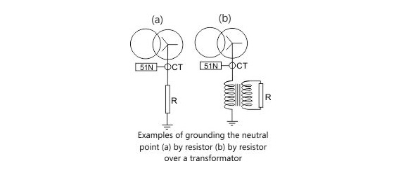
Positioned between the neutral point and ground, NGRs elevate the overall resistance in case of an earth fault, thus constraining the current to a secure magnitude.
Advantages of NGRs include:
- Reduce the single phase fault currents and secure each piece of equipment in MV electrical networks,
- Reduce the transient overvoltages which can occur during an earth fault, and be monitored and used to activate the earth fault relay,
- Increase protection of generators, transformers and related equipment,
- Reduced operation/maintenance costs,
- Increase safety,
- Provide simple, reliable, selective means of protection,
- Allows the use of equipment, and in particular cables with lower insulation levels than for an insulated neutral scenario
- Reduce the step voltage
The fault current value should be limited to a value that can be safely handled by the machine or transformer. It also needs to be high enough to be sensed by the earth fault protection relays. If the NGR resistance value is too high, the fault current will be very low and will not be able to activate the earth fault protection relay during earth fault conditions.

In a three phase star connection, the capacitances are formed with the ground. In the event of an earth fault, these capacitances may get charged with the line voltage and may cause transient overvoltages. The NGR should have a value that permits a let-through current which enables the capacitances to discharge.
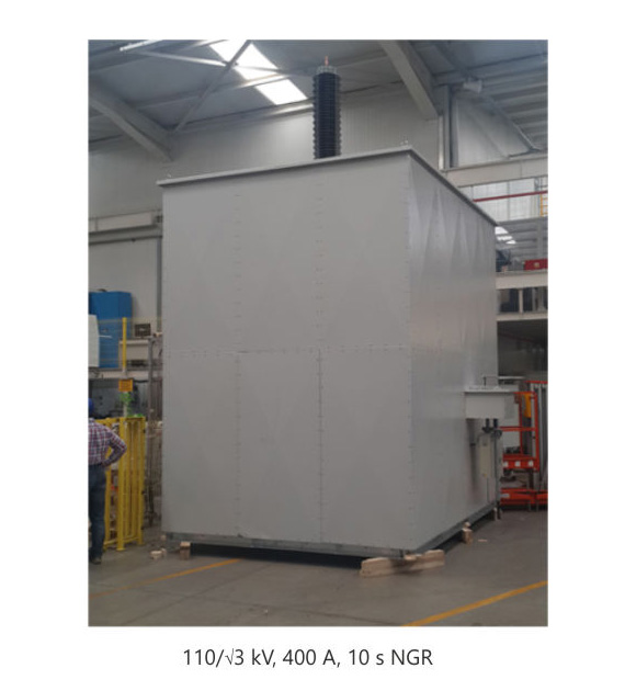
The resistances are also categorized by the time that they can withstand the fault current. Typical durations are 5-10 seconds. The extended time rating resistors are used in systems where the reliability of the system is critical, e.g. petroleum industries, mines, etc. In these situations, high resistances are used for withstanding long periods of earth fault. When an earth fault occurs in one phase, an alarm will be generated. However, the system continues to run until the next scheduled shutdown.
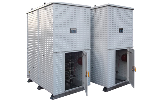
Hilkar Neutral Earthing Resistors are designed to absorb a large amount of energy without exceeding temperature limitations defined in IEEE 32. Hilkar NGRs can be used in both indoor and outdoor settings. The neutral point is connected with a porcelain bushing or a high voltage (XLPE) cable, typically (minimum cross-section = 70mm2 copper or 95mm2 aluminium) from the bottom, top or side. The most common protection degree preferred for NGRs is IP 23 as it allows the resistor elements to cool more easily. Because the resistor elements are comprised completely of stainless steel, they are capable of withstanding extreme environmental conditions and thus suitable for both the seashore and desert. NGRs are shipped with maintenance and installation guidelines which include recommended relay settings. Hilkar provides complete technical assistance in order to meet your specifications or site conditions.
NGR Options
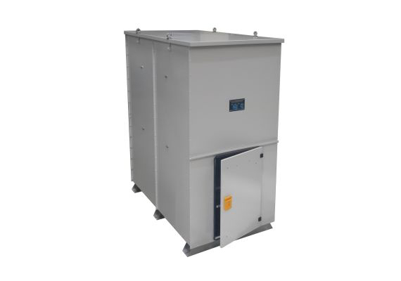
- Elevated support stands are provided for ground clearance and safety
- Specially designed units for hazardous and extreme locations (Ex-proof, ATEX certified)
- Stainless steel or aluminium enclosures on demand
- Installation of voltage transformers
- Installation of protection relays
- Porcelain entrance bushings can be mounted on the top or on the side of enclosure
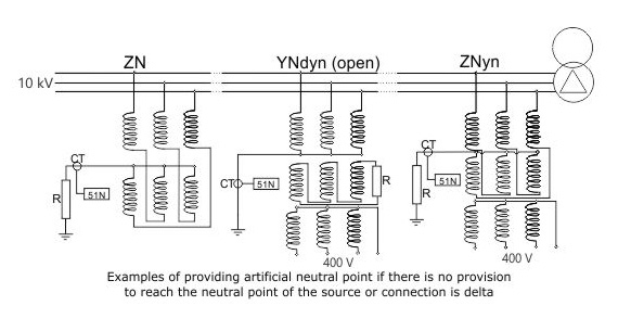
- Grounding transformer installation
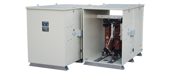
- Motorized or manual single pole disconnector switches, load break switches, vacuum contactors, circuit breakers, surge arresters and heaters in the Neutral Grounding Resistors