Nonlinear loads such as power electronics-based equipment and electric furnaces are sources of harmonic currents that can lead to harmonic distortion. This is one of the most important parameters for defining the power quality. Most commercial and industrial loads (ex. personal computers, photocopy machines, power supplies, compact fluorescent lamps, AC and DC motor drives), inject harmonic currents into the networks they are connected to.
Harmonic distortion in a network causes:
- Equipment heating
- Insulation failure due to overheating and higher voltage peaks than rated fundamental voltage (50Hz or 60Hz) sinusoidal signal
- Equipment malfunction (false zero cross detection on power electronic devices)
- Communication interference
- Fuse and breaker mis-operation
Passive harmonic filters are the most commonly used devices for reducing harmonic distortion in a network. They are built from passive RLC components, i.e. resistors, inductors and capacitors.
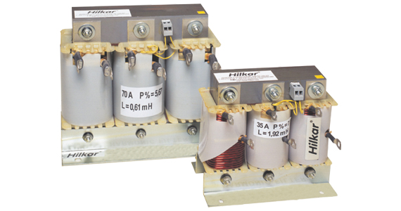
At low voltage level, iron core reactors are typically used as harmonic filter inductors. They may be also used at medium voltage level in some applications.
Together with the capacitors existing in the harmonic filter, the reactors in these filters serve to provide a resonance path. By appropriately tuning the resonance frequency of a harmonic filter, the unwanted harmonic currents injected by the nonlinear loads can be prevented from entering the electrical grid.
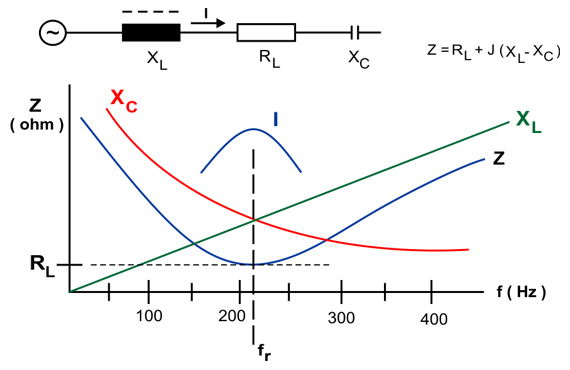
In the design stage, calculations of both the series resonance (the frequency at which the filter impedance becomes minimum) and the parallel resonance (the frequency at which the equivalent network and filter impedance becomes maximum) are important. In practice, the most commonly used filter type is a single-tuned filter which consists of the series connection of a capacitor and a reactor. For this configuration, series resonance frequency is calculated as follows:
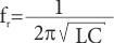
where, L is the inductance of reactor in Henries, and C is the per phase equivalent capacitance of the capacitor bank in Farads. On the other hand, the ratio of the reactor's reactance to the capacitor's reactance at the fundamental frequency is called the p factor.
fr = 134 Hz for p = 14%
fr = 189 Hz for p = 7%
fr = 210 Hz for p = 5.64%
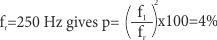
Shown above are the industrial standard values in 50Hz networks for single-tuned filters, where the series resonance frequency is not tuned to an integer multiple of the fundamental frequency, i.e. any harmonic component, but to a non-integer multiple of the fundamental frequency, i.e. an interharmonic. This configuration is called a de-tuned filter. De-tuning avoids any harmonic filtering and provides reactor power compensation, while eliminating the risk of parallel resonance with any harmonic or interharmonic component existing in the grid. It also reduces the inrush currents of the harmonic filter. However, in order to provide a series resonance frequency tuned to 5th harmonic for a 50Hz network:
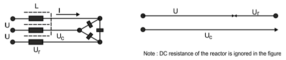
It is evident here that the series connection of the reactor and capacitor increases the amount of voltage on the capacitor above network voltage. This increase is in relation to the value of p as follows:

where Un is the network voltage and Uc is the capacitor voltage. It is important to consider this rise of voltage when choosing the voltage ratings of the capacitor bank.
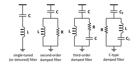
Apart from single-tuned filters, harmonic filter reactors may also be used in second order and C-type filters according to the type of load and purpose (different types of filters are given in the figure below). Moreover, when they are used in medium voltage level, they may be used in series with Flexible AC Transmission Systems (FACTS) devices such as a Static VAr Compensator (SVC) or Static Synchronous Compensator (STATCOM), in order to reduce the amount of harmonics injected by these systems into the electrical grid.
Industrial customers are required to comply with harmonic current and harmonic voltage limits with respect to voltage level and the ratio of short circuit power-to-load power, in standards such as IEEE 519.92. Therefore, careful design of the tuning frequency and rating of the reactors, which considers a wide frequency band of both the harmonics and interharmonics is important.
All Hilkar iron core harmonic filter reactors are custom designed for specific applications to provide the most efficient design at the most economical prices. Consideration of the voltage, current, inductance, type of application (or filter type), harmonics, interharmonics, size, transient events such as switchings, and required loss characteristics are always taken into account. All routine tests are performed in accordance with EN 60289 or other standards, depending on customer request. Reports are available on request and all results are submitted to customer. Basic testing programs includes some or all of the following:
- Routine Tests (Inductance, Resistance, One Minute AC Insulation Voltage Withstand Test and Impulse Voltage Withstand Test)
- Short Circuit Withstand Test
- Temperature Rise Test
- Sound Level Test
- Seismic Test