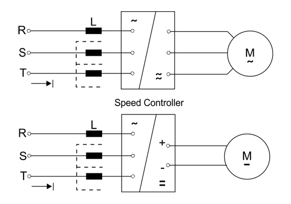
Line and load reactors are generally serial-connected to the input and/or output terminals of three phase equipment such as motor speed controllers, inverters and UPS systems. These types of equipment make use of semiconductor switches such as IGBTs, thyristors, and diodes and therefore create harmonic distortion and high switching over-voltages (dv/dt). Use of such equipment has been becoming more widespread as the technology advances. However, the negative effects should not be overlooked.
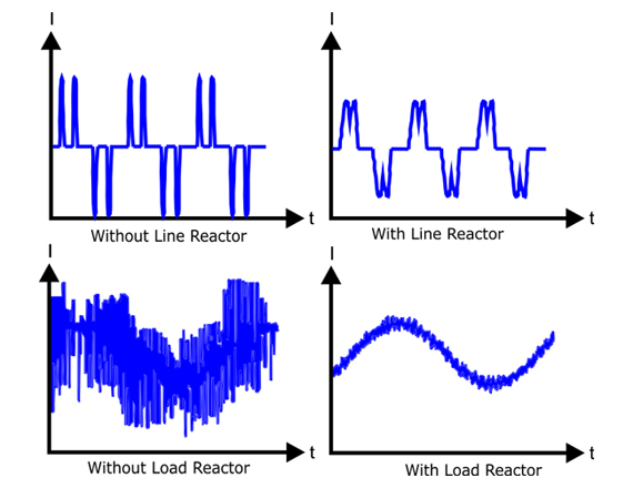
By using line and load reactors, the adverse effects that comes with using such equipment can be decreased in the following ways:
- Limited starting current
- Reduced motor noise
- Reduced motor temperature
- Reduced harmonic distortion
- Reduced motor heating
- Reduced switching over-voltages
- Easier selection of fuses as per nominal motor current
These reactors are designed in order to provide 4% voltage drop. Different voltage drop values are provided on demand.
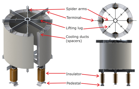
All Hilkar line and load reactors are custom designed for various and diverse. The designs take into consideration the voltage, current, inductance, type of application, harmonics, interharmonics, size, transient events such as switchings, and loss characteristics in order to provide the most efficient design at the most economical price. All routine tests are performed in accordance with IEC 60076-6 or other standards, depending on customer request. Type test reports are available on request and all reports are submitted to customer. Basic testing programs includes some or all of the following tests:
- Routine Tests (Inductance, Resistance, One Minute AC Insulation Voltage Withstand Test and Impulse Voltage Withstand Test)
- Short Circuit Withstand Test
- Temperature Rise Test
- Sound Level Test
- Seismic Test