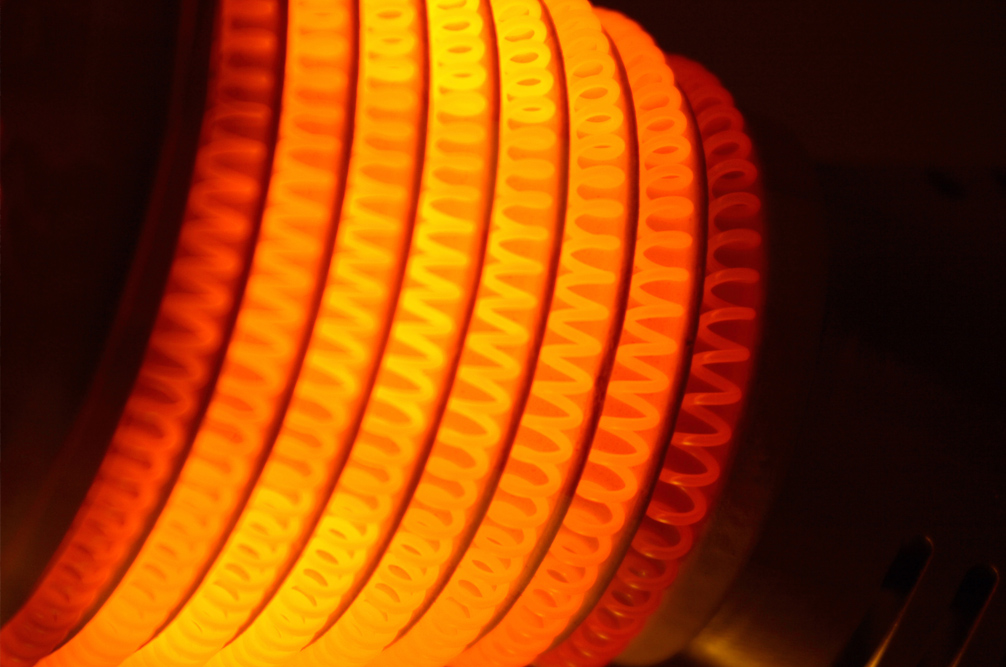
POWER RESISTORS
-
- Neutral Grounding Resistors
- High Resistance Neutral Grounding Devices
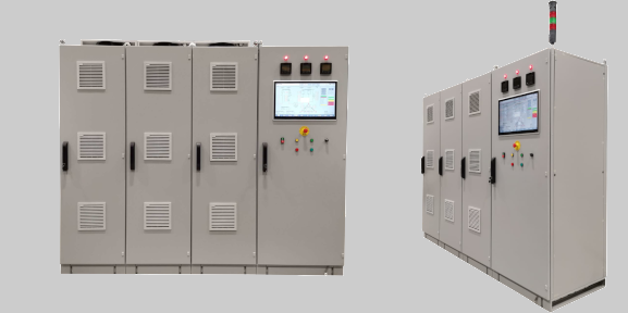
- Generator Neutral Grounding & Leads Cubicles
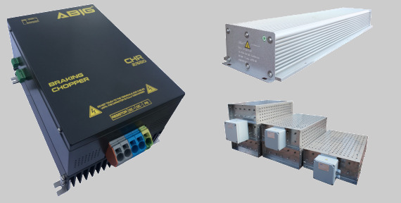
- Dynamic Braking Resistors
- Motor Starting & Control Resistors
- Harmonic Filter Resistors
- Current Limiting Resistors
- Sensing Resistors
- Crowbar Resistors
- Anti-Condensation Heaters
- Explosion-Proof Heaters
- Railway Resistive and Inductive Elements

POWER QUALITY
- Iron Core Reactors
- Motor Drives Input/Output Filters
- MV Capacitor Banks
- Surge Capacitors
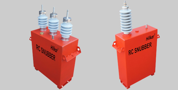
- RC Snubber Filters